Back to the Basics: Response Factors

The most notable feature of the Flame Temperature analyzer is the uniformity of response factors for a wide variety of combustible gases.
The most notable feature of the Flame Temperature analyzer is the uniformity of response factors for a wide variety of combustible gases.

Due to the special requirements of analyzer systems, a yearly audit should be performed of the following analyzer records:
This should be performed by a person who is an expert in the particular requirements of the analyzer and process, and who may be able to detect potential problems that otherwise might go undetected.

The most reliable method to test the sensor system is to inject a known concentration of test gas, as during calibration, and observe the reading and alarms.
In all analyzer systems, there is a possibility of undetected faults which might disable the analyzer's safety function. Therefore the greater the frequency of calibration and test, the lower the probability of an undetected analyzer fault.
Automated test and calibration features in computer-based analyzer systems economically allow increased frequency of calibration and test, increasing reliability.

Analyzers designed to industry standards incorporate malfunction indicators and relay outputs for most potential detectable faults, such as:
It is essential to connect these to the control system so that the operator is notified and the process reverts to a safe condition during an analyzer malfunction.
While programmable controls and computers provide a great degree of convenience, unless these controls can be shown to conform to strict standards for the use of programmable devices in safety systems, it is preferable to use hard-wired connections for the critical alarm and analyzer malfunction signals.

Where an analyzer’s signal controls the ventilation rate, it is particularly important to prevent a false control system during the “zero” portion of calibration, where zero gas is injected to the analyzer, forcing the analyzer’s signal to 0% LFL.
This would force the control system to reduce ventilation to an unsafe level, since the analyzer, for the duration of the zero calibration, reports a false low solvent concentration.
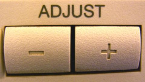
In normal uses, most analyzers will require adjustment to their sensitivity to make up for a gradual reduction in sensitivity over time.
The normal amount of adjustment of the signal should be well understood by the maintenance personnel so that problems other than loss of sensitivity are not corrected by the improper use of the "span" adjustment.
For Example:

Safety standards often require that, the analyzer must produce an alarm whenever the solvent concentration exceeds 60% LFL or some level that leaves a margin of safety. All analyzer systems should have provisions that prevent alarm levels without enough of a safety margin.
All alarms and deviations from expected operation are opportunities to determine if a fault exists in the process or analyzer system.
An alarm which activates when the rate of increase in solvent concentration exceeds the rate alarm level, can give early warning when a severe upset condition exists that is likely to eventually result in a very high solvent concentration.
Because the alarm triggers on a change in reading per second, and not a reading level, the rate alarm can activate at the very beginning of the analyzer's response time rather than several seconds or more later when the reading has finally climbed above the warning or danger alarm levels.

A positive test for correct operation of critical alarms is essential.
At a minimum this should be performed as part of a regular yearly audit that includes verification of the alarm relays, alarm annunciators, fault relays and all corrective actions, including: